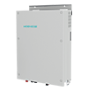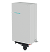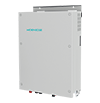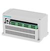
In our commercial PV projects, one of the most frequent architectural debates is whether to use a split DC bus or a single DC bus. We have seen both approaches succeed—and fail—depending on the project's voltage requirements, fault tolerance needs, and expansion plans. Here is how we evaluate which topology fits a given 15kW PV DC-DC converter application.
Engineering teams frequently debate whether split or single configurations deliver superior performance across mid-scale commercial deployments. Resolving this architectural dilemma requires examining electrical stresses and control complexities unique to modern solar installations.
Commercial developers must weigh capital expenditures against long-term operational resilience before finalizing hardware topologies for remote generation sites. Power electronics specialists evaluate reactive current paths and insulation coordination to prevent premature component degradation during operational transients.
Balancing these technical variables ensures that chosen layouts support stable energy transfer without introducing unwanted harmonic distortion or common-mode noise. Rigorous pre-construction modeling prevents expensive redesign cycles during later integration phases.
Bipolar split configurations divide the intermediate voltage link into positive and negative rails separated by a virtual center tap or physical neutral conductor. Such layouts facilitate multi-level inverter interfacing and reduce voltage stress across individual semiconductor switches during high-voltage DC distribution phases.
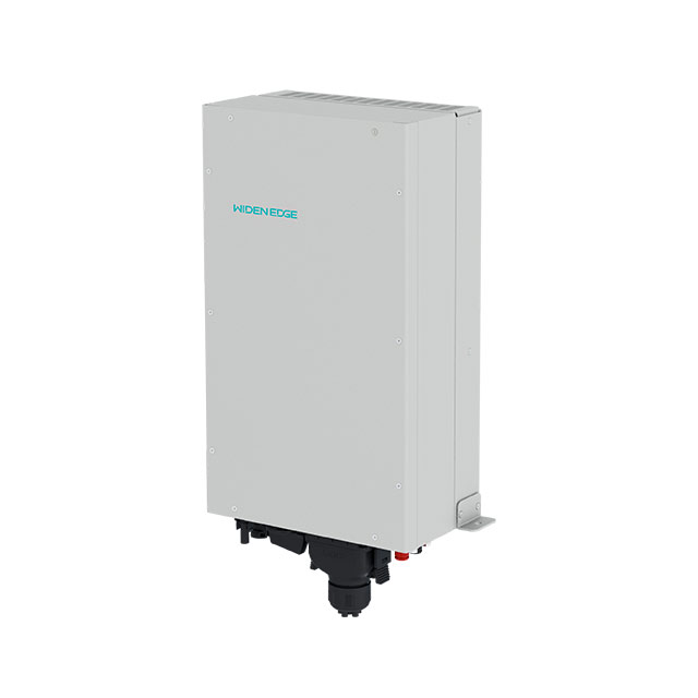
Implementing a specialized 15kW PV DC-DC converter within a split bus environment requires precise control over positive and negative rail voltage symmetry. Maintaining equilibrium across both halves prevents circulating currents from distorting overall system efficiency and thermal profiles.
Unipolar single bus architectures maintain a single high-voltage rail paired with a common ground reference, simplifying control loops and reducing magnetic component counts. Simpler topologies lower initial manufacturing overhead and streamline firmware development for manufacturers producing standardized commercial energy hardware.
Integrating any standard dc dc converter in pv system applications becomes straightforward when designers eliminate the need for dual-rail balancing circuits. Simplicity, however, can introduce trade-offs regarding fault containment, common-mode filtering demands, and voltage utilization ranges.
Unbalanced string generation or asymmetric shading across photovoltaic arrays naturally forces split buses to experience differential voltage drift between rails. Active voltage balancing circuits or dedicated software algorithms must constantly inject corrective compensation currents to maintain stable mid-point potentials.
Neglecting this dynamic balancing requirement triggers overvoltage conditions on lightly loaded rails, threatening sensitive capacitors and switching transistors with catastrophic failure. Robust fault detection mechanisms remain mandatory whenever split configurations manage variable generation profiles.
Fault tolerance capabilities differ drastically between bus architectures during sudden short-circuit events or ground fault occurrences in remote arrays. Split networks allow localized protection devices to isolate faulted sections without entirely shutting down healthy power conversion branches across the microgrid.
Technicians benefit from compartmentalized fault isolation because maintenance crews can diagnose specific sub-circuits while adjacent generation blocks continue operating uninterrupted. Operational continuity makes split arrangements attractive for mission-critical industrial microgrids demanding zero unplanned downtime.
Isolating faults within a dual-rail environment minimizes system-wide voltage sags, protecting downstream loads from experiencing severe power quality disturbances. Advanced protection coordination protocols ensure that fault currents remain within safe thermal and magnetic thresholds during transient clearing periods.
Field engineers must calibrate protective relays meticulously to account for split-bus grounding configurations and potential earth-leakage current paths. Proper grounding design prevents nuisance tripping while maintaining compliance with international electrical safety standards.
Single-rail topologies excel at maximizing conversion efficiency by reducing the number of active semiconductor stages required to step up photovoltaic voltages. Fewer switching nodes translate directly into lower conduction and switching losses during peak solar generation hours across large array fields.
Maximizing every percentage point of conversion efficiency directly improves the financial payback period for commercial asset owners and system operators. Maximizing conversion performance requires careful thermal management to prevent semiconductor junction temperatures from exceeding safe operational limits.
Operating unipolar buses under high input voltages places greater electrical stress on the primary switching transistors housed inside every deployed 15kW PV DC-DC converter unit. Engineers must select higher voltage-rated semiconductors or utilize multi-stage topologies to handle elevated DC bus potentials safely without risking dielectric breakdown.
Selecting robust components offsets some of the initial cost savings gained from simplifying the underlying bus layout architecture. Careful component rating prevents premature hardware aging under continuous thermal and electrical stress.
Thermal dissipation design becomes particularly challenging in unipolar layouts due to concentrated power losses across fewer active semiconductor devices. Implementing advanced liquid cooling loops or optimized forced-air heat exchangers ensures that junction temperatures remain within stable operational boundaries during peak loads.
Engineers analyze thermal cycling profiles extensively to ensure that high-density single-rail systems achieve their targeted operational lifespans without unexpected degradation. Effective heat rejection directly safeguards system reliability in hostile outdoor operating environments.
System designers must evaluate site-specific geographical constraints, local grid codes, and safety regulations before committing to a final DC bus layout strategy. Projects situated in remote environments requiring extensive DC cable runs often favor split configurations to reduce copper losses through higher distribution voltages.
Conversely, compact installations prioritizing low maintenance overhead and straightforward wiring protocols lean heavily toward unipolar arrangements. Tailoring hardware topologies to match environmental realities ensures long-term asset reliability and predictable energy yields.
Selecting an appropriate dc dc converter in pv system layouts dictates how effectively a microgrid manages fluctuating renewable inputs during off-grid operations. Equipment suppliers offering flexible hardware platforms allow engineering firms to adapt bus voltages based on evolving project specifications and regional regulatory updates.
At WidenEdge, our engineering team designs advanced conversion technologies focused on maximum architectural adaptability and robust field longevity. Comprehensive technical support ensures that complex microgrid deployments achieve optimal performance regardless of bus topology choices.
Return